

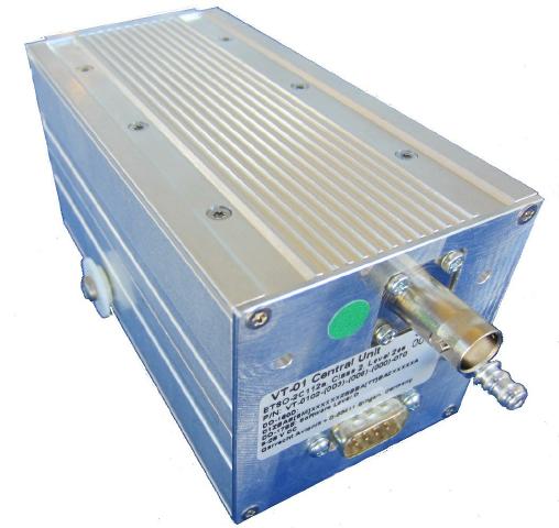
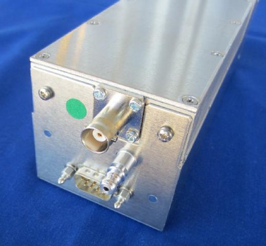
Items delivered include: The transponder unit as pictured, matching DB9 connector and shell, EASA approval certificate.
Items required for a full installation:
a) Power supply circuit breaker / overload protection
b) Antenna cable and suitable transponder antenna
c) Connection to a supported EFIS via CAN interface (Single pair twisted wire)
d) Connection to a matching GPS NMEA feed for ADS-B out (optional)
Simple to install, just connect power, CAN interface to the EFIS (both on the DB-9 connector) and connect the antenna.
MGL Avionics stocks both class-1 and class-2 types
VT-0102-125 Class 1 up to 40.000ft
VT-0102-075 Class 2 up to 15.000ft
The VT-0102 transponder is connected to a compatible EFIS via CAN interface. The following EFIS systems are compatible:
Garrecht Avionics Remote mode-S transponder
Please note: This product is no longer available from MGL Avionics. The Garrecht interface required for interfacing is no longer available. Information presented here is for reference only.
Voyager G2, Odyssey G2, iEFIS Discovery, iEFIS Explorer, iEFIS Challenger, iEFIS Discovery, IEFIS MX1.
Connection to Voyager G2, Odyssey G2
Connect to the built in CAN interface port if no other items are connected to this port. In the EFIS setup, select "Garrecht transponder" as option for the CAN interface.
If the CAN interface is used to connect other items (MGL autopilot servos, AHRS, compass, RDAC etc), you must use a MGL Avionics "CAN-CAN bridge unit" or a "MGL REM-T1" remote control head to connect the Garrecht transponder to the EFIS. This provides the required protocol isolation between the devices. It is not possible to use the Garrecht transponder AND a MGL CAN bus device on the same CAN bus without a protocol isolator.