Ok - I need a little education/confirmation. New to MGL and CANBUS in general. If Anyone can help would be great!
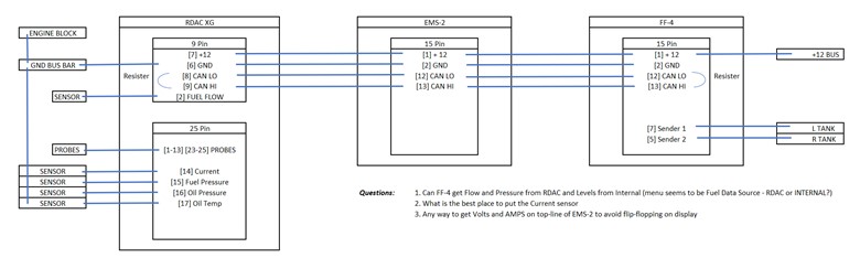
The wiring schematic in the EMS-2 manual seems to show a 1200 ohm resister between the CAN LO and HI pins to be added to the DB connectors on both ends of the twisted pair cable between the EMS and the RDAC, so:
1) There is a small bag of screws and resisters etc. in the EMS box. Is this what the two small resisters are?
2) if I daisy chain RDAC XG to EMS-2 to FF-4 I would add the resistors at the RDAC and FF-4 only, nothing on the EMS-2 in the middle correct?
3) if I chain these as above can the FF get fuel flow and pressure from the CANBUS/RDAC but fuel levels from direct wiring (since they are at the panel already from existing fuel gauges)
Additional questions:
4) the supplied larger DB connector and cable sure doesn’t look like it should be in an engine area and it likely doesn’t have terminating resister either. Any reason I can’t use a terminal block type DB connector and just screw the sensor wires to the connector? Would keep things pretty clean.
5) lastly, I’m confused on grounds. If the RDAC ground is connected to engine case, probe negatives just connect to RDAC terminals and oil temp/press grounds to airframe right? I saw mention of needing a ground bus in one of the documents for one of the other RDAC models. If using RDAC must EMS-2 ground still be connected directly to engine block? Can you clarify preferred approach?
Thanks.
EMS-2 and RDAC XG
Forum rules
Please keep your posts friendly and on topic. No politics or discussions of a controversial nature not related to our favorite subject of flying and avionics. Offending posts may be removed or moderated.
Please keep your posts friendly and on topic. No politics or discussions of a controversial nature not related to our favorite subject of flying and avionics. Offending posts may be removed or moderated.
Re: EMS-2 and RDAC XG
Valsoar wrote: ↑Sun Nov 29, 2020 1:21 am Ok - I need a little education/confirmation. New to MGL and CANBUS in general. If Anyone can help would be great!
The wiring schematic in the EMS-2 manual seems to show a 1200 ohm resister between the CAN LO and HI pins to be added to the DB connectors on both ends of the twisted pair cable between the EMS and the RDAC, so:
1) There is a small bag of screws and resisters etc. in the EMS box. Is this what the two small resisters are?
yes. 120 ohms. You need two (short runs say up to 10-15 feet or so do fine with just one of them anywhere).
Normally you would daisy chain anyway you like (short stubs are quite OK) and fit a resistor on each end of the bus (a maximum of two 120 ohm resistors, never more) - as stated just one of them is quite OK even though not technically correct.2) if I daisy chain RDAC XG to EMS-2 to FF-4 I would add the resistors at the RDAC and FF-4 only, nothing on the EMS-2 in the middle correct?
Yes.3) if I chain these as above can the FF get fuel flow and pressure from the CANBUS/RDAC but fuel levels from direct wiring (since they are at the panel already from existing fuel gauges)
Additional questions:
4) the supplied larger DB connector and cable sure doesn’t look like it should be in an engine area and it likely doesn’t have terminating resister either. Any reason I can’t use a terminal block type DB connector and just screw the sensor wires to the connector? Would keep things pretty clean.
as long as it is located in an area where it is not exposed to excessive heat or water, oils etc quite OK. Some create a small protected compartment.
NEVER connect ANYTHING to the airframe. The only permitted connection is ONE ground cable usually from battery negative to some point on the airframe and that one is mandatory. You must never allow any electrical DC currents to flow in an airframe - this creates all sorts of issues. Galvanic corrosion is just one of them.5) lastly, I’m confused on grounds. If the RDAC ground is connected to engine case, probe negatives just connect to RDAC terminals and oil temp/press grounds to airframe right? I saw mention of needing a ground bus in one of the documents for one of the other RDAC models. If using RDAC must EMS-2 ground still be connected directly to engine block? Can you clarify preferred approach?
View it from the RDAC's side: The RDAC measures voltages with respect to its own ground. So any grounded probes must be connected to the same ground point as the RDAC. The engine block serves as this ground point.
The danger with mixing and sharing grounds is that in many aircraft quite large ground currents can flow (landing lights and other high current users, battery charging from regulators etc). This causes small voltage drops on your various ground wires - if not wired correctly these voltage drops add or subtract to the voltage drops on the probes (depending on polarity) - this can lead to very significant measurement errors - in particular with probes where the voltages are small to start with.
Re: EMS-2 and RDAC XG
Thank you, so here is where I think I'm headed then:
The GND bus bar shown would be for the RDAC only and is isolated from the airframe so that all attached sensors and the RDAC are essentially direct to the Engine.
The reason the grounds are confusing is that the standard VANS set up for the oil and fuel pressure sensors is a firewall mounted manifold as follows:
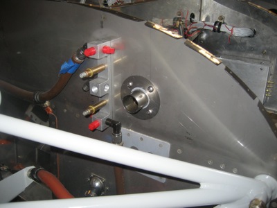
So, the sensors would normally be grounded to the airframe by virtue of the manifold mount. So do I really need to isolate the manifold from the firewall in order to ground the sensors solely via the above RDAC Ground bus that is connected to the Engine or can I just connect the manifold to the RDA ground bus which in turn will be connected to the engine block. The manifold is the standard VAN's method. Trying to understand whether it would create a problem the MGL instrumentation?
Since the FF-4 is going where one of the old fuel gauges was, I was hoping just to pick up the existing sensor wires and connect directly to the FF-4, but the set-up menu seems to be FUEL DATA SOURCE - RDAC or INTERNAL - so is it even possible to have a mixed source - fuel levels from Internal and pressure and flow from RDAC or do I need to run the sender wires back out through the firewall to the RDAC in the engine compartment?
Thank you again for all the assistance.
The GND bus bar shown would be for the RDAC only and is isolated from the airframe so that all attached sensors and the RDAC are essentially direct to the Engine.
The reason the grounds are confusing is that the standard VANS set up for the oil and fuel pressure sensors is a firewall mounted manifold as follows:
So, the sensors would normally be grounded to the airframe by virtue of the manifold mount. So do I really need to isolate the manifold from the firewall in order to ground the sensors solely via the above RDAC Ground bus that is connected to the Engine or can I just connect the manifold to the RDA ground bus which in turn will be connected to the engine block. The manifold is the standard VAN's method. Trying to understand whether it would create a problem the MGL instrumentation?
Since the FF-4 is going where one of the old fuel gauges was, I was hoping just to pick up the existing sensor wires and connect directly to the FF-4, but the set-up menu seems to be FUEL DATA SOURCE - RDAC or INTERNAL - so is it even possible to have a mixed source - fuel levels from Internal and pressure and flow from RDAC or do I need to run the sender wires back out through the firewall
Thank you again for all the assistance.
Re: EMS-2 and RDAC XG
Unfortunately it is quite common to see all sorts of equipment using the airframe as convenient ground - after all that's how its done on cars right ?
Well, remember when Land Rovers changed to the aluminium clad version (now you had a nice mixture of metals) - these things would corrode before your eyes.
Now the currents from your level senders are not huge - but they are DC and they will pass various types of metal junctions on the way back to the battery. Give it enough time and there will be consequences.
One aircraft type (I shall not elaborate on the make) used the wings and fuselage as ground return for the landing lights. Now we have a bit more current. All the experts where scratching their heads why this aircraft would show signs of severe corrosion all over the place within a few months. Many remedies and expensive corrosion protection chemicals where tried - to exactly zero effect.
That's one side of the story - the other is that often in modern avionics systems very small amounts of high frequency signals are conducted on the power supply wiring and also other wiring - now imagine what happens if a ground wire from some equipment that has a tiny RF signal on the ground wire gets connected to the airframe - you turn a fly into an elephant. The entire fuselage is now nothing more than some weirdly shaped antenna. That small signal that under ordinary circumstances is unnoticeable can now be a major source of radio receive interference.
The last item - the RDAC and any similar engine monitoring system from other makers will certainly want to measure voltages from various probes (including your fuel level senders - it will send a current down the line and measure the voltage drop on your sender). Now the RDAC will measure between its own ground and that of its sender input. What if the ground of the sender is 0.1V different from that of the RDAC - that can easily happen - you can have large ground current say form alternators charging your battery to landing lights etc flowing through various wired ground connections - even though the resistance of these is low - you can easily drop some voltage and the RDAC can now see a different voltage to what is actually at the probe.
In your case you can isolate the senders but likely it will not make a huge difference in a "normal" installation where supply grounds have been correctly routed with all this in mind.
Re: EMS-2 and RDAC XG
Crap, now I’m completely lost.
Engine is nicely grounded to firewall single pass-through bolt (the other side of which is the battery connection and a “forest”).
But, Vans transducer manifold attaches directly to firewall (as shown in my previous post) and isn’t electrically isolated from it - its metal sensor to metal manifold to metal firewall. Can I simply run a ground wire from the body of the manifold (despite its connection to the firewall) and then another from the engine case to a common connection to the RDAC ground bus? Or for the MGL to work do I need to scrap the firewall mounted manifold all together and instead use isolated (insulated) mounts such as so that the sensors are ONLY connected to the RDAC ground bus?
Or perhaps a better way to put it - am I less likely to find myself fighting install issues if I go with the isolated engine mount attachments than with the non isolated firewall manifold attachment?
Apologies if I’m sounding like an idiot on this, Lots of folks using the vans manifold but if I’m understanding correctly this “could” cause problems for the MGL RDAC as its metal to metal with the firewall. I’d prefer to minimize the likelyhood of battling gremlins. I’d rather not do this twice and luckily haven’t drilled any holes in the firewall so still time to change direction.
Thanks for all the invaluable advice. I’m learning a lot here and truly appreciate the obvious time and effort put into support here.
Engine is nicely grounded to firewall single pass-through bolt (the other side of which is the battery connection and a “forest”).
But, Vans transducer manifold attaches directly to firewall (as shown in my previous post) and isn’t electrically isolated from it - its metal sensor to metal manifold to metal firewall. Can I simply run a ground wire from the body of the manifold (despite its connection to the firewall) and then another from the engine case to a common connection to the RDAC ground bus? Or for the MGL to work do I need to scrap the firewall mounted manifold all together and instead use isolated (insulated) mounts such as
so that the sensors are ONLY connected to the RDAC ground bus?Or perhaps a better way to put it - am I less likely to find myself fighting install issues if I go with the isolated engine mount attachments than with the non isolated firewall manifold attachment?
Apologies if I’m sounding like an idiot on this, Lots of folks using the vans manifold but if I’m understanding correctly this “could” cause problems for the MGL RDAC as its metal to metal with the firewall. I’d prefer to minimize the likelyhood of battling gremlins. I’d rather not do this twice and luckily haven’t drilled any holes in the firewall so still time to change direction.
Thanks for all the invaluable advice. I’m learning a lot here and truly appreciate the obvious time and effort put into support here.
Re: EMS-2 and RDAC XG
Finishing instal of MGL EMS extreme on my Lycoming RV4. Using my JPI flow can transducer, I can not get any fuel flow readings. MGL technical said to try and omit the 5.6k ohm resistor as specified in the lycoming addendum they supply, but no luck. Any suggestions. I’d rather not have to put the old JPI gauge in there when I’ve spent time and money with this MGL EMS.
Re: EMS-2 and RDAC XG
It's certainly not going to do anything without a pull up resistor. Wire the resistor between the transducer signal line and +12V supply. Using the +5V from the RDAC may not give you enough voltage swing.
You should be able to get a clean pulse train that has only two possible levels: close to zero volts or whatever the pull up resistor is connected to. Connect a volt meter and move some fuel through the sender - while fuel is moving you will get some form of "in between" value (average voltage) and as flow stops it will either settle at the high or low value depending on where the impeller stops.
You should be able to get a clean pulse train that has only two possible levels: close to zero volts or whatever the pull up resistor is connected to. Connect a volt meter and move some fuel through the sender - while fuel is moving you will get some form of "in between" value (average voltage) and as flow stops it will either settle at the high or low value depending on where the impeller stops.
Re: EMS-2 and RDAC XG
That transducer appears to have several wires so I guess that body is not connected to ground in the sensor. If it is - likely not a train smash. It's solidly connected to the frame and that will have a very low resistance. That frame should have a really low resistance to the engine block. There should not be any electrical currents of concern in that frame.Valsoar wrote: ↑Sun Dec 06, 2020 1:21 am Crap, now I’m completely lost.
Engine is nicely grounded to firewall single pass-through bolt (the other side of which is the battery connection and a “forest”).
But, Vans transducer manifold attaches directly to firewall (as shown in my previous post) and isn’t electrically isolated from it - its metal sensor to metal manifold to metal firewall. Can I simply run a ground wire from the body of the manifold (despite its connection to the firewall) and then another from the engine case to a common connection to the RDAC ground bus? Or for the MGL to work do I need to scrap the firewall mounted manifold all together and instead use isolated (insulated) mounts such as
Or perhaps a better way to put it - am I less likely to find myself fighting install issues if I go with the isolated engine mount attachments than with the non isolated firewall manifold attachment?
Apologies if I’m sounding like an idiot on this, Lots of folks using the vans manifold but if I’m understanding correctly this “could” cause problems for the MGL RDAC as its metal to metal with the firewall. I’d prefer to minimize the likelyhood of battling gremlins. I’d rather not do this twice and luckily haven’t drilled any holes in the firewall so still time to change direction.
Thanks for all the invaluable advice. I’m learning a lot here and truly appreciate the obvious time and effort put into support here.
Of importance is the ground of the RDAC - all its measurements related to probes that are grounded are done with respect to its own ground. As long as there is no voltage difference between the ground at the sensor and the ground of the RDAC you are just fine. Any difference however will add or subtract form what the RDAC sees. The polarity depends on the direction of the unwanted current. Anything has a resistance. It might be small but it can have an effect if the current is large. A current of just 10A (say from a landing light) flowing through a connection that has just 0.1 ohms will drop a whole volt !!! That can exceed the entire measurement range of interest of a typical NTC temperature probe for example.
On some probes - like typical NTC oil temperature senders we are starting to look at a few milli-volt at higher temperatures where the NTC resistance is small. Just a few mill-volt added or subtracted from that because of a small voltage difference between ground connections will introduce a large error in measurement - just at the range of temperatures you are interested in.
That is the reason we like the RDAC supply ground to come directly from the engine block and that wire must not be shared with any other electrical user or system. In this case we are guaranteed that we can measure accurately. Only the small RDAC supply current will flow in this wire and that will have a tiny effect of no concern with even just a modest diameter cable.